Published Book on Amazon
| All of IOT Starting with the Latest Raspberry Pi from Beginner to Advanced – Volume 1 | |
| All of IOT Starting with the Latest Raspberry Pi from Beginner to Advanced – Volume 2 |
출판된 한글판 도서
| 최신 라즈베리파이(Raspberry Pi)로 시작하는 사물인터넷(IOT)의 모든 것 – 초보에서 고급까지 (상) | |
| 최신 라즈베리파이(Raspberry Pi)로 시작하는 사물인터넷(IOT)의 모든 것 – 초보에서 고급까지 (하) |
Original Book Contents
25.5.6 LED Light
LED (Light-emitting diode) is widely used as a oupput device for determining whether electricity flows through a specific line when constructing an electronic circuit. LED lights up when the voltage is applied, so it can indicate whether the specific GPIO port of the Raspberry Pi is high or low, and can determine if electricity flows on a certain line of the circuit. The GPIO port of Raspberry PI does not provide high power enough to drive high-brightness LED, so buy low-power LED (typical LED) when purchasing LED.
The following is a LED part picture and a description of LED basic structure. Long leg is (+) and short leg is (-).
When installing LED on a breadboard, insert the LED's long leg (Anode, +) into one row of breadboards and short leg (Cathode, -) into the other row. Do not put both legs in the same row. Then connect the long leg (+) of the LED to the (+) side of the circuit and the short leg (-) of the LED to the (-) side of the circuit.
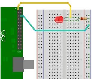
Below is an example of constructing a circuit by using LED. The yellow wire connects the long leg (+) of LED to GPIO 1 pin that supplies 3.3V power, and the blue wire connects the short leg (-) of LED through a resistor to GPIO 3 pin, which functions as a GND.
|
|
LEDs will burn out if excessive currents or voltages are applied, so it is required to limit current and voltage using appropriate resistor. The maximum voltage and current that is normally used in LED is as follows. Outside this range, LED will be damaged. The data below shows that according to the color, allowable current is same and the longer the wave length is, that is, the closer to the red color of visible light it is, the less the permissible voltage is.
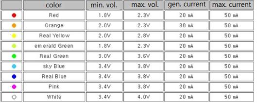
Table 25‑3 LED Feature by color
A resistor is used to lower the voltage, but if the resistance is too large, the brightness of the light is too dark or not at all, and if it is too low, the LED can be burnt, so a resistor of suitable resistance value is required. It is necessary to know the forward maximum current (I) and the forward maximum voltage (F) that can flow through the LED to calculate the appropriate resistance value. To calculate the resistance value that can lower the voltage to the desired level, use the following formula. This is to calculate the resistance value to lower the actual voltage applied to the circuit where the LED is installed to the level of voltage that the LED can tolerate.
R = (V – F) / I R -- resistance value in ohm unit
V -- Voltage applied to LED
F -- Allowable forward maximum voltage of LED
I -- Allowable forward maximum current of LED
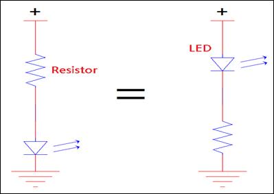
The position for installing the resistor for protecting a LED is normally set on the (+) side based on the LED, but the same effect can be obtained and there is no problem even if the LED is installed on the (-) side. In other words, either left or right in the figure below has the same effect.