Published Book on Amazon
| All of IOT Starting with the Latest Raspberry Pi from Beginner to Advanced – Volume 1 | |
| All of IOT Starting with the Latest Raspberry Pi from Beginner to Advanced – Volume 2 |
출판된 한글판 도서
| 최신 라즈베리파이(Raspberry Pi)로 시작하는 사물인터넷(IOT)의 모든 것 – 초보에서 고급까지 (상) | |
| 최신 라즈베리파이(Raspberry Pi)로 시작하는 사물인터넷(IOT)의 모든 것 – 초보에서 고급까지 (하) |
Original Book Contents
25.8.2 Measuring Temperature with Digital Sensor DS18b20
25.8.2.1 Features of DS18B20 Sensor
There are many sensors to measure temperature on the market, but Raspberry Pi does not have an ADC (analog to digital converter), so analog temperature sensors like TMP36 can not be used directly.
Here we will measure temperature by connecting the digital sensor DS18B20 directly to Raspberry Pi.
There are several kinds of DS18B20 sensors available on the market. There are some original circular sensors as shown below, and there are some sensors that DS18B20 sensors have been slightly modified so that they can be easily used on an experimental interface board such as Arduino. Both have all the same performance and features, but with slightly different array locations of connector. Considering only the position of the pin, everything is the same whatever you use
|
|
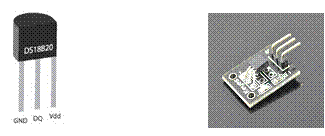
original sensor modified sensor
| No | original sensor | modified sensor | feature |
| 1 | GND | - | ground |
| 2 | Vdd | + | power |
| 3 | DQ | S | data line |
Figure 25‑20 Digital temperature sensor DS18b20
The DS18B20 has the following features.
| Item | Description |
| Interface | Use 1-Wire bus interface method |
| Voltage range | 3.0V to 5.5V |
| Power supply method | external supply available, parasite power available (power supply via data line) |
| Operating temperature | -55°C to +125°C (-67°F to +257°F) |
| Measurement error | ±0.5°C from -10°C to +85°C |
| Thermometer resolution | User Selectable from 9 to 12 Bits |
| Digital conversion | 12-Bit Digital Word in 750ms (Max) |
| Using Resistor | weak pullup resistor, 4.7 K ~10 K ohm |
The DS18B20 uses a 1-Wire bus protocol developed by Maxim, which is a bus communication method using one control signal, and the microprocessor (the master device) identifies devices connected to the bus and issue commands with a 64 bit code assigned to each device. This means that multiple devices can be connected to one bus simultaneously. In this method, there is no conceptual limit to the number of devices that can be connected on one bus.
|
|
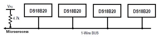
In the DS18B20, the control line requires a weak pull-up resistor because all devices are connected to the bus via a 3-state or open-drain port (DQ pin of DS18B20). Usually a pull-up resistor of 4.7KΩ or 10KΩ is used.
The DS18B20 sensor can use an external power supply, but can operate the sensor without using a separate power supply by using parasite power mode. The parasite power mode refers to the method of supplying power to the sensor using the data line used to transmit the temperature measurement value. This method supplies power to the sensor itself using the current supplied to the data line. In the following figure, the left side shows a case using an external power source and the right side shows a case using a parasite power mode.
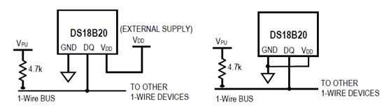
In parasite power mode, when the bus is "HIGH" state, the power supplied through the pull-up resistor is supplied to the sensor via the DQ pin. It supplies power to the internal capacitor (CPP) when the bus signal is "HIGH" state and supplies power to the internal device when the bus is "LOW" state.
For more detailed information on the DS18b20, please refer to the followings:
■ http://datasheets.maximintegrated.com/en/ds/DS18B20.pdf
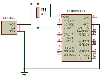
25.8.2.2 Connection between Raspberry Pi and Sensor
The DS18B20 sensor using a 1-Wire protocol is installed in parallel to the bus. All sensors use the same data pin. Connect the data line to pin 7 (BCM port 4) of Raspberry Pi.
Use a pull-up resistor on the data line, using a 4.7KΩ to 10KΩ resistor. Even if multiple sensors are installed at the same time, it is necessary to install only one pull-up resistor.
The following is a case of configuring the circuit in the manner that supplies external power to the sensor by using the 3.3V power supplied from pin 1 of Raspberry Pi.
25.8.2.3 Enabling 1-Wire Bus Protocol
Raspbian/Occidentalis supports 1-Wire bus protocol used by the DS18b20. If you want to use 1-Wire protocol, you need to activate the protocol first.
To enable 1-Wire protocol, first add the following in "/boot/config.txt" file.
| ~ Skip # Activate 1-Wire protocol dtoverlay=w1-gpio |
Modify "config.txt" file and reboot the system. If "/sys/bus/w1/" folder is created, it is normal processing.
| pi@raspberrypi ~ $ ls /sys/bus -l |
| ~ Skip drwxr-xr-x 4 root root 0 Jun 14 22:51 spi drwxr-xr-x 4 root root 0 Jun 14 22:17 usb drwxr-xr-x 4 root root 0 Jun 14 22:51 w1 drwxr-xr-x 4 root root 0 Jun 14 22:51 workqueue |
If the folder is not created, activate the device with the following procedure using "modprobe" command, and verify that the above "/sys/bus/w1/" folder is created again.
| sudo modprobe w1-gpio |
| sudo modprobe w1-therm |
25.8.2.4 Interface File for Measuring Value of DS18B20
When the 1-Wire bus protocol is activated normally and the Raspberry Pi and sensor are connected, the measured value from the sensor is interfaced to the specific file of Raspberry Pi. The interfaced data is generated under "/sys/bus/w1/devices" folder.
Check the contents of the folder to see if a folder of "28-xxxxxx" format is created. This folder refers to a specific sensor installed in the 1-Wire bus protocol. If this folder is created, it indicates that Raspberry Pi is normally connected to the sensor and interfaces measurement data of sensor.
The temperature values measured by the sensor are stored in "/sys/bus/w1/devices/28-xxxxxx/w1_slave" file.
|
|
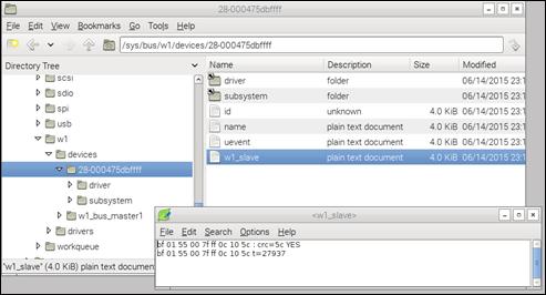
If you check the contents of the file, it will have the following format.
| be 01 55 00 7f ff 0c 10 1f : crc=1f YES be 01 55 00 7f ff 0c 10 1f t=27875 |
Here, the data of "t=nnnnn" format in the second line is Celsius temperature degree measured by the sensor and the value divided by 1000 is used. The above value will be "27.875 CEL".
25.8.2.5 Writing Program to Process Temperature Value
Here we will write a program that reads the data interfaced to "/sys/bus/w1/devices/28-xxxxxx/w1_slave" file of Raspberry Pi and displays it on the screen.
We use uses Python 3 for program development language. Start Python 3 IDLE, write the following Python program, and save it in "sensor_temP_DS18B20.py" file.
| import os import glob import time
# os.system('modprobe w1-gpio') # os.system('modprobe w1-therm')
w1_device_dir = '/sys/bus/w1/devices/' w1_data_dir = glob.glob(w1_device_dir + '28*')[0]
w1_device_file = w1_data_dir + '/w1_slave'
def read_temp_raw(): f = open(w1_device_file, 'r') lines = f.readlines() f.close() return lines
def read_temp(): lines = read_temp_raw() while lines[0].strip()[-3:] != 'YES': time.sleep(0.2) lines = read_temp_raw()
equals_pos = lines[1].find('t=') if equals_pos != -1: temp_string = lines[1][equals_pos+2:] temp_c = float(temp_string) / 1000.0 temp_f = temp_c * 9.0 / 5.0 + 32.0 return temp_c, temp_f
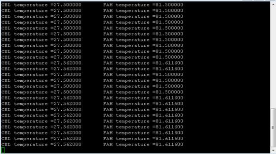
while True: print("CEL temperature =%f \t FAH temperature =%f" %read_temp()) time.sleep(1) |
Here is a look at the contents of the above program.
■ This sets the device file that interfaces with the sensor to "/sys/bus/w1/devices/28-xxxxxx/w1_slave".
■ This reads the file repeatedly until the first line of the file has the value "YES" at the end.
■ When a temperature measurement value comes in, this reads the value starting with "t=" and convert it to CEL temperature and FAH temperature.
■ This prints CEL temperature and FAH temperature.
Execute the following program with "sudo" command on Terminal screen. The temperature value measured by the sensor will then be displayed continuously on the screen.
| sudo python sensor_temp_DS18B20.py |