Published Book on Amazon
| All of IOT Starting with the Latest Raspberry Pi from Beginner to Advanced – Volume 1 | |
| All of IOT Starting with the Latest Raspberry Pi from Beginner to Advanced – Volume 2 |
출판된 한글판 도서
| 최신 라즈베리파이(Raspberry Pi)로 시작하는 사물인터넷(IOT)의 모든 것 – 초보에서 고급까지 (상) | |
| 최신 라즈베리파이(Raspberry Pi)로 시작하는 사물인터넷(IOT)의 모든 것 – 초보에서 고급까지 (하) |
Original Book Contents
25.4.5 Pull-up Resistor and Pull-down Resistor
In many electronic circuits, it is the pull-up resistor and pull-down resistor that are used as one of the methods to safely protect the circuit from being broken down from various electrical shocks and to ensure that it can operates correctly according to the originally designed intention under any circumstances. Basically, the pull-up resistor and pull-down resistor are a term defined by where to equip the resistor between power supply and ground, and allow a small current to flow by using a resistor of appropriate size for each resistor. Next, we will explain this.
For additional reference, please refer to the followings:
■ http://www.resistorguide.com/pull-up-resistor_pull-down-resistor/
■ https://learn.sparkfun.com/tutorials/pull-up-resistors
■ http://www.seattlerobotics.org/encoder/mar97/basics.html
25.4.5.1 Floating State
Computer represents information by 1 (High) and 0 (Low). When expressing information in an electronic circuit connected to a chip, a voltage corresponding to input information is applied to an input pin. That is, the highest voltage represents 1 (High), and the lowest voltage represents 0 (Low). If you want to express 1 (High), you apply the highest voltage. If you want to express 0 (Low), you apply 0V. In this way, it is possible to operate normally only when the value received by the pin is 1 (High) which receives the highest voltage or 0 (Low) which is connected to GND and receives the lowest voltage.
Depending on the micro-controller, the voltage used can be different. Normally, 5V is used for the highest voltage and 0V is used for the lowest voltage. Raspberry Pi uses 3.3V as the highest voltage.
However, when the voltage of the input pin is neither the highest voltage nor the lowest voltage, it can not be determined whether it is 1 (High) state or 0 (Low) state. This state is said to be floating. That is, Floating state is the state in which nothing is connected or isolated from each other.
In general, if the line is not connected, it is easy to think that it is in a state of 0 (Low) because electricity does not work, but it is not true. Electronically, if nothing is connected, the voltage of the input pin may be intermediate voltage between the highest voltage and the lowest voltage, or it may vary into a high state or a low state at any time depending on the peripheral electric field state or various noises. In this way, if the input value is the unstable and frequently changing, digital input/output may be interrupted, and the component may malfunctions.
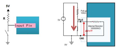
Figure 25‑7 Electronic Circuit of floating state
The above left figure is the circuit that the input pin is connected to GND. When the switch is on, 0V (Low) is input, but when the switch is off, it is not possible to know whether the input is 5V or 0V. This state is called floating
The above right figure is the circuit that the input pin is connected to the 5V power supply. When the switch is on, 5V (High) is input, but when the switch is off, it is not possible to know whether the input is 5V or 0V. This state is called floating.
25.4.5.2 Why to Use Resistor in Pull-up/Pull-down State
For example, suppose you create a circuit that is high if you do not press a switch and low when you press a switch.
|
|
To do this, it would be possible to create a circuit like the one shown on the left above. Let's check that there are no problems. In this case, because the input port of the MCU (micro-control unit) at point "1" is in the high impedance state (HIGH-Z), it is not possible to know whether it is in the high state or the low state
So this time, if you make the circuit as shown on the right above, when the switch is turned on, too much current flows from Vcc to GND. This can cause a lot of heat, which can burn parts and wires or cause a fire. Moreover, most of the circuitry can fail because the voltage on the power supply drops to zero level. This overcurrent can damage the microcontroller with a huge impact, and if it is connected directly to the ground, it could short out and burn the wire.
In order to prevent such a danger, it is possible to prevent a short as described above by limiting a small current to flow by using an appropriate-sized resistor between the power supply and the GND as shown below. The left side is a pull-up resistor and the right side is a pull-down resistor.
25.4.5.3 Pull-up Resistor
In the digital circuit, there is a logic circuit that logically maintains a high state when the switch is normally off, and maintains a low state when the switch is on.
To make such a circuit, the resistor connected between the input or output terminal of the signal and the + VCC power terminal is called a pull-up resistor. It is called 'pull-up' because it means that the pin is suspended at a high resistance. A resistor is placed on the 5V power side, and a switch is attached on the lower ground side. On the other hand, the input pin is in the state of high impedence and a high resistance is operating.
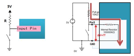
Let's consider the case where the switch is normally off in this circuit. A fairly large pull-up resistor of 10 KΩ installed on the power supply side provides only a small current that is limited enough to not damage the circuit. All supplied current flows to the input pin.
Inside of the input pin is in a high impedance state, where typically higher resistance than 10 times resistance of the pull-up resistor is operating. In this connection state, pull-up resistor and internal resistance of input pin are connected in series, so very little voltage drop occurs in the pull-up resistor, but most of the voltage is distributed to the internal resistance of the input pin. Therefore, the input pin maintains High state, which is the highest voltage.
The input pin of the micro-controller usually has an input impedance of about 100KΩ to 1MΩ. Therefore, when the switch is off, the voltage applied to VCC is divided by the pull-up resistor R1 and the internal impedance R2, and the value distributed to R2 becomes the value appearing at the input pin. If the pull-up resistor value is large on the level of a few MΩ, the voltage across R2 may be relatively small, and in the worst case may not be recognized as High in the program. To prevent this problem, pull-up resistors usually use resistors less than 1/10 of the input pin's impedance. This will cause most of the voltage to be applied to R2, so that the voltage at VCC will appear almost at the value of the input pin.
Now let's review the state when the switch is on. When the switch is closed, there is no resistance on the GND side and high resistance of high impedance is working on the input pin side. Therefore, all the current supplied from the power source flows to the GND side, and since the input pin is also connected to the GND, All currents flow to GND and the input pin is kept at a low voltage of 0V.
In addition, this isthe form that power supply and GND are directly connected, but since the current is limited to low level with pull-up resistor, it is possible to maintain stable state without shorting electrically. In this way, using pull-up resistor allows the circuit to keep high state when the switch is off, and to keep low state stably when the switch is on.
This pull-up resistor has different features depending on the resistance value. If the resistance value is high, the current consumption is low but the noise resistance is low. On the contrary, when the resistance value is low, the current consumption is high, but it is advantageous in noise and speed.
25.4.5.4 Pull-down Resistor
In the digital circuit, there is a logic circuit that logically keeps the low state when the switch is normally off, and keeps a high state when the switch is on.
To make such a circuit, the resistor connected between the input or output terminal of the signal and the ground terminal is called a pull-down resistor. It is called 'pull-down' in the sense that it always ties the pin to the ground. A switch is placed on the 5V power side, and a resistor is attached on the lower ground side. On the other hand, the input pin is in a high impedance state and a high resistance is operating.
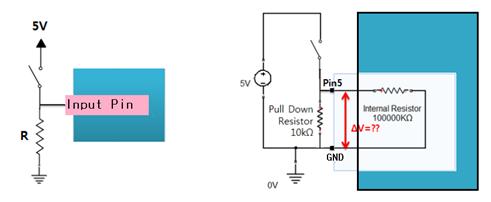
Figure 25‑9 Pull-down resistor
Let’s consider the case where the switch is normally off in this circuit. Since the input pin is connected to GND, all the current remaining at the input pin flows to GND, and the voltage of the input pin becomes 0V.
|
|
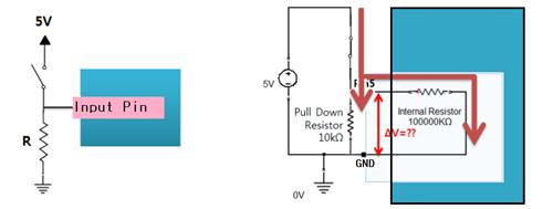
Now let's review the state when the switch is on. When the switch is closed, the current flowing from the power supply flows simultaneously to the pull-down resistor and the input pin.
There is a pull-down resistor on the GND side and the inside of input pin is in a high impedance state, where usually higher resistance than 10 times esistance of of the pull-up resistor is operating. Since the pull-down resistor value is much smaller than the resistance of the input pin, most of the current supplied from the power supply flows to the GND side, and a small amount of current flows to the input pin side. However, the voltage of the power supply is equally applied to the pull-down resistors and the input pin.
In addition, this state is a form in which the power source and the ground are directly connected, but since the current is limited to a low level with the pull-down resistor, it is possible to maintain the stable state without shorting electrically. In this way, using pull-down resistor allows the circuit to keep a low state always when the switch is off and to keep a high state stably when the switch is on.
This pull-up resistor has different features depending on the resistance value. If the resistance value is high, the current consumption is low but the noise resistance is low. On the contrary, when the resistance value is low, the current consumption is high, but it is advantageous in noise and speed.
25.4.5.5 Resistance Value of Pull-up Resistor
The appropriate resistance value of the pull-up resistor is limited by the following two factors.
The first factor is power consumption. If the resistance is too low, a lot of current flows through the pull-up resistor when the switch is closed, causing the device to generate heat and unnecessary current consumption. This condition is called strong pull-up (more current flows) and is a condition that should be avoided when low power consumption is required.
The second factor is the pin voltage when the switch is open. If the pull-up resistor value is too high, the input voltage may be insufficient when the switch is opened in combination with a large leakage current at the input pin. This condition is called weak pull-up (less current flows). The actual resistance value of pull-up resistor depends on the impedance of the input pin, which is closely related to the leakage current of the input pin.