Published Book on Amazon
| All of IOT Starting with the Latest Raspberry Pi from Beginner to Advanced – Volume 1 | |
| All of IOT Starting with the Latest Raspberry Pi from Beginner to Advanced – Volume 2 |
출판된 한글판 도서
| 최신 라즈베리파이(Raspberry Pi)로 시작하는 사물인터넷(IOT)의 모든 것 – 초보에서 고급까지 (상) | |
| 최신 라즈베리파이(Raspberry Pi)로 시작하는 사물인터넷(IOT)의 모든 것 – 초보에서 고급까지 (하) |
Original Book Contents
25.5.4 Resistor
25.5.4.1 Meaning of Resistor
A resistor is an electronic component that has the effect of dropping voltage by interrupting the flow of current so that the current does not flow well in the electric circuit. It is often used in most electronic circuits. The unit of resistance is ohm (ohm), which is denoted by Ω.
There are various kinds of resistor depending on the characteristics. A fixed resistor is the most commonly used resistor and have a constant resistance value that does not fluctuate. A variable resistor is a resistor that allows a variable resistance value within a certain range. It is used for volume control part or other control part, and there are a rotation type and a slide type. In addition, some of them are lead type or some chip types depending on the shape of the resistor.
|
|
Generally, when constructing a test electronic circuit, a lead type fixed resistor is often used. In electronic circuits, resistors of various resistance values are required. Therefore, it is preferable to prepare multiple resistors of resistance value that is widely used. It is also a good idea to buy a kit that are being sold with a bundle of several types of resistors together
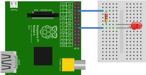
The following shows a simple example of using a resistor when configuring a circuit.
25.5.4.2 Reading Resistor Value
If you want to know the resistance value of a resistor, you should measure it with a multimeter or calculate it with a colored band. Here, we describe how to calculate the resistance value with the color band on the resistor surface.
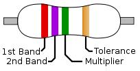
Below is a resistor of typical four-color band pattern. In the four-color band, the first two bands represent the resistance value. The third color band is the multiplier, which indicates by how many powers of 10 the previous two-digit resistance value is to be multiplied. The last 4th color band represents the error tolerance or precision of the resistance value. There is also a resistance marked with five color bands. In this case, the resistance is the first three digits, the fourth is the multiplier, and the fifth is the tolerance.
|
|
| Color | Figure | Multiplier | Tolerance | Heat Coefficient | ||
| Black | 0 | 1 | ||||
| Brown | 1 | ×101 | ±1% | F | 100 | S |
| Red | 2 | ×102 | ±2% | G | 50 | R |
| Orange | 3 | ×103 |
| 15 | P | |
| Yellow | 4 | ×104 | (±5%) |
| 25 | Q |
| Green | 5 | ×105 | ±0.5% | D | 20 | Z |
| Blue | 6 | ×106 | ±0.25% | C | 10 | Z |
| Violet | 7 | ×107 | ±0.1% | B | 5 | M |
| Gray | 8 | ×108 | ±0.05% (±10%) | A | 1 | K |
| White | 9 | ×109 |
|
| ||
| Gold |
| ×10-1 | ±5% |
|
| |
| Silver |
| ×10-2 | ±10% | K |
| |
| None |
|
| ±20% | M |
| |
Table 25‑2 Reading resistor value
Let's read the resistor values in the figure above. Since the first two colors are red and red, the resistance value can be viewed as 22. The next one is green, so it means 5th power of 10. Then it becomes 2,200,000Ω. 1,000Ω is 1KΩ and 1KΩ is 1MΩ, so it is usually convenient to write it at 2.2MΩ. The last color band is gold, so the tolerance is +-5%.